
3.3 Central 3D View
The center of the software is the 3D viewport display area, mainly including the build plate, the view and section tools, and the build plate viewport buttons.
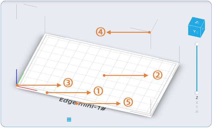
-Build Plateform, the plate consists of ① physical virtual plate, ② printable indication zone, ③ coordinate axes, ④ plate outline, and ⑤ machine model, wherein the sizes of the physical virtual plate and the plate outline are the actual printable size of the equipment; the size of the printable indication zone is the "actual printable area" minus the "margin values configured by the software on the frontend and backend"; the coordinate axes are consistent with the actual printing coordinate axes; the machine model is consistent with the equipment model name in "Print Parameter Settings".
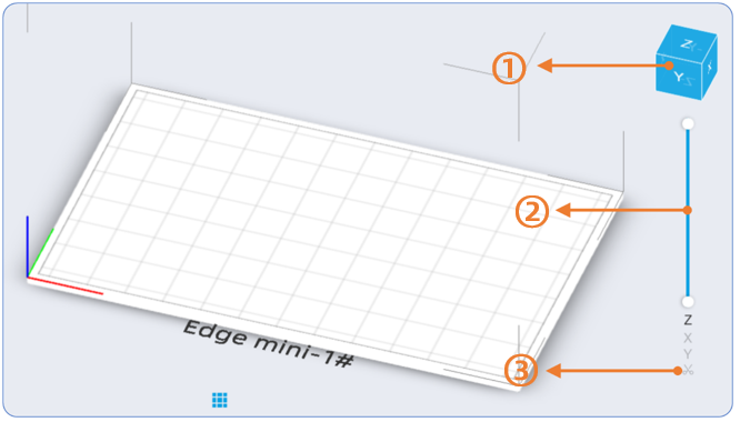
-View and Section Tools, this area consists of ① view rotation knob, ② section inspection axis, and ③ section clipping button, wherein the view rotation button is synchronized with the rotation of the build plate view; you can hold down the right mouse button and rotate this knob to adjust the build plate button, or click the faces, edges, or corners of this button to switch the viewport; the section inspection axis defaults to the Z-axis section, and you can adjust the slider with the mouse to determine the section, enter a height value to determine the section, or press the "PgUp" and "PgDn" buttons on the keyboard to quickly determine the section. The X and Y directions can be operated in the same manner; the section clipping button is mainly used in conjunction with the section inspection axis, and when a specified section is selected, you can click this button to quickly clip and split the specified model.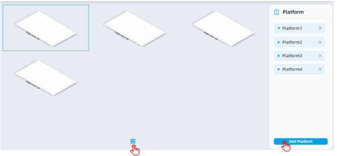
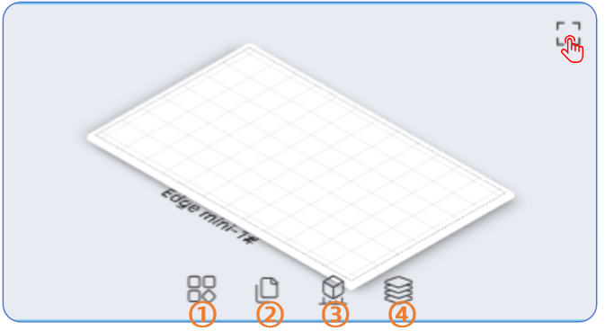
-Build Plate Viewport Buttons, clicking them will display the multi-plate interface (shortcut key "Space"). The software supports creating up to 9 plates within the same software window, and different "Print Parameter Settings" can be selected respectively. In this way, when printing different materials and other parameters for the same case, pre-processing tasks can be established separately using different plates directly within the same software window. In addition, rapid workflow processing of models can be performed within the multi-plate window; clicking the four buttons corresponds respectively to ① "Quick Auto-Arrange Parts", ② "Quick Hollow + Honeycomb + Drain Holes", ③ "Quick Add Support", and ④ "Quick Slice" operations. It is not recommended for users to perform data processing on more than 3 plates simultaneously, as the computer configuration requirements are relatively high and the calculation time is relatively long. Clicking the "□" button in the upper right corner of a designated plate (or pressing the Space key again) can enlarge and focus on that plate.
-Right-click operation, when a designated model is selected, you can right-click the mouse to perform manual operations on the model, mainly including "Delete", "Duplicate", "Grid", "Move to Bottom", "Mirror", "Separate/Merge", "Combine and Connect", and "Move Between Plates" operations.
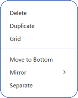
1)Delete operation, you can left-click the designated model to select it, or hold down the "Ctrl" key to select multiple models, and right-click to choose Delete, which will remove the model (group) from the platform;
2) Duplicate operation, you can left-click the designated model to select it, or hold down the "Ctrl" key to select multiple models, and right-click to choose Duplicate, then the model (group) will be automatically copied and pasted onto the current platform;
3) Grid operation, you can left-click the designated model to select it (note that the grid operation can only be applied to a single model file), and right-click to choose Grid; a preview of the model will appear in the specified direction, and both the direction and the grid quantity can be adjusted with the mouse. After confirmation, left-click the mouse to complete the grid operation;
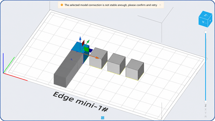
4)Move to Bottom the model file will automatically move to the bottom after being imported. During moving operations, if the shortcut moving operation is used, its height value will not change; however, if a height value in the Z direction is entered, the model will be lifted to the specified height. At this time, if the model needs to be attached to the bed, you can right-click and select Move to Bottom;
5) Mirror operation, you can left-click the designated model to select it, or hold down the "Ctrl" key to select multiple models, and right-click to choose horizontal or vertical mirror, then the model (group) will generate a mirrored model (note that the original model will not be retained);
6) Merge and Separate operations, when 2 or more models are selected, right-clicking the mouse can display the "Merge" button, allowing the selected model group to be merged (i.e., multiple .stl format models are merged into one .stl format model). Conversely, if there are several individul shells within a single model, right-clicking the mouse can display the "Separate" button, allowing the selected model to be separated (i.e., one .stl format model is separated into multiple .stl format models).
7) Combine and Connect operation, when 2 or more models are selected, right-clicking the mouse can display the "Combine and Connect" button, allowing the selected model group to be merged and perform model connection;
8) Move Between Plates operation, when there are 2 or more plates within the same software window, you can left-click the designated model on the current plate to select it, or hold down the "Ctrl" key to select multiple models, and right-click to choose the "Move to" button, then the model (group) will be automatically transferred to the specified plate.